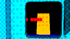
 [a]
Thermal sources (0.1-in rad.) at 1, 2, 3, 4, & 6 arc-min,
viewed from the center of the first lens surface. There are 4
sources aligned behind the 3 arc-min source at ~1-inch intervals.
Camera efl=65 mm.
[a]
Thermal sources (0.1-in rad.) at 1, 2, 3, 4, & 6 arc-min,
viewed from the center of the first lens surface. There are 4
sources aligned behind the 3 arc-min source at ~1-inch intervals.
Camera efl=65 mm.Infrared Array Camera (IRAC) Tasks
 [a]
Thermal sources (0.1-in rad.) at 1, 2, 3, 4, & 6 arc-min,
viewed from the center of the first lens surface. There are 4
sources aligned behind the 3 arc-min source at ~1-inch intervals.
Camera efl=65 mm.
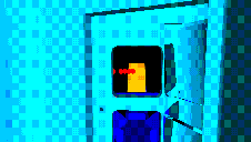 [b]
[b] 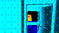 [c]
[c] 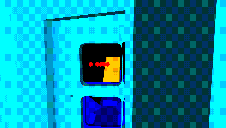 [d]
[d]
[b] Same as [a] with 25 mm camera efl. [c] View from LEFT lens
surface. [d] - RIGHT lens surface.
The reflections in the calibration mirror on the right are less
important than direct views.
 [e] Calibration mirror closed, looking into the
calibration source.
IRAC - Potential Stray Light
Sources Viewed Past Pick-off Mirror
(Preliminary
APART Model Results)
The small images are about 5 kbytes
each, linking to larger images of about 40 kbytes.
IRAC Instrument Development Model - Stray Light Suppression
I-DEAS 3D solid models of the IRAC (and SIRTF Telescope to Focal Plane) have been translated to IGES representation and installed in AutoCAD 13 drawings as 3D surface models. The AutoCAD 3D models will be used to generate an APART input file for stray light analysis. This section represents the interpretation of first results after carefully looking at the 3D models.
[A] A series of images looking from the center of Detector 3 to the center of the Pupil Stop; and a series of images looking from the corner of Detector 3 to the center of Detector 1.
[B] A series of images looking from the center of the first surface of the Aspheric Lens to the center of the Pick-off Mirror.
[C] A top view of the IRAC IDM showing potential stray light paths.
 [8-120]
  [8-005]
  [9-11]
 [9-16]
The index images are about 1.5k .GIFs (110 wide x 80 high, pixels). The full size images are 10-15k .GIFs (652 wide x 456 high, pixels).
[8-120 & 8-005] Shaded perspective images seen from the center of an IRAC detector with a decreasing focal length "camera." The distance from the cameral lens to the center of the Pick-off Mirror is 296 mm. The viewpoint is about 100 microns above the front surface of the center of the upper, on-axis detector. [8-120] has a 120 mm focal length and a very narrow field-of-view. [8-005] has a 5 mm focal length and a very wide field-of-view (nearly 120 degrees). Elements identified by color, from the center outward, approximately are:
[9-11] AutoVision Ray Trace Rendered Image with all optical elements in place: A Test Target has been placed at the center of the field-of-view in SIRTF focal plane to confirm viewing location and path past edge of Pick-off Mirror.
[9-16] AutoCAD Shaded Image: Close-up of Detector / Stop / Filter / Beamsplitter