 [8-160]
 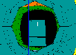 [8-120]
 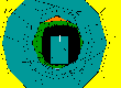 [8-080]
 [8-080s]
 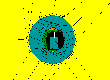 [8-040]
 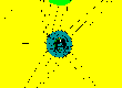 [8-020]
 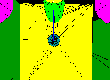 [8-010]
 [8-005]
 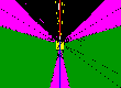 [8-001]
 The index images are about 1.5k .GIFs (110 wide x 80 high, pixels). The full size images are 10-15k .GIFs (652 wide x 456 high, pixels).
These images have been generated from the 3 -dimensional IRAC design drawings created in I-DEA Master Series 3 & 4. Those drawings include the optical ray trace of the IRAC instrument transferred from the Code-V design to I-DEA and AutoCAD via IGES procedures and files. The mechanical structures were output as parts from I-DEA to stereolithographic (STL) surface files, using batch programs written by Drew Jones, GSFC. The STL files were used as input files to a 3D modeling application, IGRIP, in the imaging laboratory of Tim Carnahan, GSFC. In IGRIP, coplanar, contiguous surfaces were joined, reducing the surface count and file sizes by just over 50 percent. IGRIP was used to generate data exchange files (DXF) which could be read into AutoCAD 13. In AutoCAD, the surfaces were grouped in logical layers for separate physical entities or parts.
The [8] series images are 3-D perspective views of the IRAC instrument from a viewpoint on the center of the upper, inline optical band. There are no transmission optical elements in place for the [8] series of images which were mainly used to set-up the imaging procedure and to look at the field-of-view immediately around the detector.
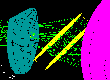
The [9] series of images are generally 3-D perspective views of the IRAC instrument from a viewpoint at the center or the extreme corner of the IRAC detector. These images have been produced using AutoVision Ray Tracing. The refractive optics, with the indices of refraction for the infrared bands, are in place and have been included in the image generation. Some AutoCAD Shaded perspective and orthographic images are included for identification of what is seen in the images.
[8-160] [8-120] [8-080]
[8-080s]
[8-040] [8-020] [8-010]
[8-005] [8-001]
The index images are about 1.5k .GIFs (110 wide x 80 high,
pixels). The full size images are 10-15k .GIFs (652 wide x 456
high, pixels).
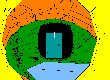
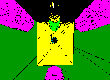
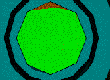
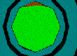
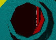
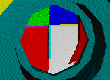
[8] Shaded perspective images seen from the center of an IRAC
detector with a decreasing focal length "camera." The
distance from the cameral lens to the center of the Pick-off
Mirror is 296 mm. The viewpoint is about 100 microns above the
front surface of the center of the upper, on-axis detector.
[8-160] has a 160 mm focal length and a very narrow
field-of-view, .... to [8-001] which has a 1 mm focal length and
a very wide field-of-view (nearly 180 degrees). Elements
identified by color, from the center outward, approximately are:
 [9-00]
 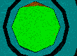 [9-01]
 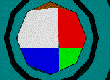 [9-02]
 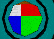 [9-03]
 [9-04]
[9-00 - 9-04] Views from the center of the detector with a test Target moved to various locations to help with image identification.
 [9-05]
 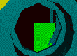 [9-06]
 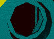 [9-07]
 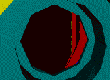 [9-08]
 [9-09]
[9-05 - 9-11] Views from the upper left corner of the detector
with changes in elements "on" and colors to help with
image identification.
[9-05] All optics are "off" showing direct path to
shutter mirror.
[9-06] Green quadrant corner of test Target. All optical elements
back "on".
[9-07 - 9-09] Changing colors to identify Pick-off Mirror,
Pick-off Mirror Support Arm seen through full optics.
 [9-10]
  [9-11]
[9-10 - 9-11] Test Target moved to center of field-of-view in SIRTF focal plane to confirm viewing location and path past edge of Pick-off Mirror.
 [9-12]
  [9-13]
  [9-14]
[9-12 - 9-14] Three orthogonal views of the test Target and the Pick-off Mirror and Pick-off Mirror Support Arm to show where the view from the corner of the detector is located.
 [9-15]
  [9-16]
[9-15] Close-up of Stop / Filter / Beamsplitter
[9-16] Close-up of Detector / Stop / Filter / Beamsplitter